Thursday, December 8, 2011

STARTERS AND ALTERNATORS

Inertia starter
An inertia starter motor works by throwing the pinion into mesh with the fly wheel at high speeds causing the engine to turn over. this is achieved by electrical current flowing through the magnetic shoes causing the armature to spin which then throw the pinion into gear. Once the pinion has forced the fly wheel into rotation the side of drive would change, making the pinion clutch engage retracting the pinion.

Pre-engaged starter
This starter works and relys on the solinoid which uses a lever/linkage to enguage the pinion before it starts to spin, this system means that there is minimum wear on the teeth.

Alernator
An alternator is an electromagnetic unit that is driven by a belt from the motor this means it wont run under its oun power. This is a rotor that cuts the magnet feild made by the coil and shoes, it turns within a stationary set of conductors called a stator. As the rotor is driven it cuts through the magnetic field causing the current to change producing an alternating current. This current changes due to the different polarity of each side of the magnet. This current is then feed through a rectifier which stabilises the voltage to a direct(DC) current. The alternator is used to power the electrical systems of the engine once started and charge the battery so it produces around 14 + V

BUISNESS PRACTICE

Warranties
When you buy a product e.g. an outboard it may come with a description of what it will do for how long but in the fine print it might say you have to run the engine on non synthetic oil and stay under 5000 revs and to flush it out for 7 minutes minimum. it is important to read all of the small print because a warrant is a legal document that assures you that it is going to work properly.

Guaranties
a guarantee is what the name is - if you buy a new part or have a new part installed professionally, the workmanship and life of the part being installed is usually guaranteed, so if the new part were to fail you wouldn't be expected to pay unless you did something against what the legal warranty said.

Quotations and estimates
A quotation is an agreement between both parties of what the job will cost this can be a range from x to y  but if the final price exceeds this you may be facing legal charges.
An estimate is a rough guess of how much you think the job will cost, this is not a legal bond like a quote so it is important that you make yourself clear to the customer what you are giving them so there is no grey areas.

Charge out rates
when deciding on a charge out rate it is important to take into account your overheads, employers and yourself. All those into consideration a $60 per hour charge out rate is not so steep.

Courtesy arrangements
these can be anything from cleaning the inside and outside of the car, checking tyre pressures, cleaning the inside if headlights, giving the customer a ride home (if local) and even offering a temporary car whilst theirs is getting fixed. All are done to keep the business turning over and money coming in.

Cultural issues
Because the world today is not split into races and cultures it is important to accomodate for difficulties, these  refer to expectations, Practises, Communication issues e.g. being clear on the phone etc.

MARINE TRANSMISSIONS

Outboard gear box
This system runs from a pinion wheel directly from the engine which turns 2 gears at the same time, however only one is ever engaged and driving (under power) by way of a dog clutch.
The gears are selected by a selector rod which has a slot on a slant that moves the dog (that is fixed to the prop shaft) into the desired forward or reverse gear.
the gears are helical tapered gears which run directly onto the prop shaft.

Stern leg system
Unlike the outboard gearbox the stern leg transmission is vertically positioned on the shaft that drives the prop shaft. The clutch system unlike the outboard dog with teeth the stern leg clutch is a tapered system that will engage either forward or reverse depending on the position of the selector shaft.
At the end of the drive shaft where the prop shaft joins is a pinion wheel and one or two permanently engaged gears - if the engine is duo prop or single props.

Inboard gearbox
An inboard gearbox uses hydraulic fluid to compress a clutch pack which therefor engages the prop to move forwards or backwards. The concept of this system is much like a motorbikes.

What type of gears are used in stern legs and outboards?
tapered helical cut gears are used in outboards and stern legs because the offer the best contact between teeth all the time especially on the pinion - this type of gear also reduces noise.

The duo prop system
This works by having a pinion drive and two constant mesh gears rotating in opposite directions and moving one shaft inside the other. a propeller is fixed to each of the shafts which are rotating in different directions, this means that one of the propels has to be cut counter rotational drive so the engines props are always moving the boat the same way whilst the props are not.

The "V" drive system.
this gear box is to change the direction of the drive shaft, it also enables you to focus the majority of the engines weight further back in the boat. it does this through 2 stages in the gear box
1. the drive shaft enters the gear box and drives the first stage which is 2 shafts the first one is the one that the drive shaft is turning, it has straight cut teeth that drive a chain that turns the next shaft which also as well as having the straight cut teeth and chain linkage, has a tapered helical cut gear on the end of it so it acts like a pinion.
2. the second shaft drives the output or third shaft on the helical cut tapered gear - allowing for the change in direction.

Jet unit and Surface drive.
A jet unit has a water intake on the bottom of the boat, the water is then pushed through a prop in the tube causing the water to exit under very high pressure (enough to push a boat). this type of drive is very effective if you are going over shallow sand bars or shallow rivers etc.
A jet unit is especially good at turning this is achieved by moving a cap over the water out put and directing it  to where ever you want without loosing power, this is why a jet boat can turn almost 180 degrees without moving.
The downside to a jet boat is that you have to be under power to maneuver the boat otherwise you will just drift.
A surface drive works on the theory that the more you have in the water the more drag you have and the slower you will go. a surface drive always has one blade out of the water at any time, this is so you accelerate faster, there is less drag and you use less fuel.


Tuesday, November 22, 2011

Gear BOX ;D

What type of gears are used for a reverse manual gear box? Explain?
in the Toyota 3k/4k gear boxes we were stripping and rebuilding the reverse gears were straight cut instead of helical cut gears this is because the reverse gear runs off of a neutral third sprocket which fits in between the driven and driver to change the way the output shaft is rotating. if the gears we helical cut it would make it very difficult to mesh 3 gears, whereas straight cut teeth slide straight in.

What type of gears are used for all the forward gears in a manual gear box? Explain?
the type of gears used in a manual gearbox to go forward are all helical style gears this is because more than one tooth is engaged at one time making it quieter than straight cut gears and stronger because of the amount of gear that is meshing with one another, this however causes thrust because of the angle of the teeth meaning thrust bearings are required. On heavy duty equipment like bulldozers etc a herringbone cut gear is used this is because more than one gear is engaged at one time and there is no thrust pressure on the shaft.

What is the purpose of a syncromesh unit? Explain
The purpose of a syncro mesh unit is to make the gear changes smooth. The name gives its job away -
it makes sure that the theeth on the two gears about to be enguaged or meshed together are spinning at roughly the sames speed so that your gears dont clunk as they mesh at different speeds. The way that the two gears are slowed to rotate at the same speed is with the brass baulk ring (a brass ring with a row of teeth and a tapered face). it is brass so that the soft metal will wear out faster than the hard shaft, it is also cheeper to replace. it is tapered because two tapers grip extremely thourghly but can also split easily.

How do you check a baulk ring for serviceability?
to check a baulk ring you need to see how close the ring is to the gear if it is able to touch the gear, the taper on the baulk ring has worn down too much, there needs to be a gap. (measured with a feeler guage) The gap would suggest that the tapers are tight against eachother and would do their job.

what is the pupose of a baulk ring?
the purpose of a baulk ring is to mach the speed of the two gears about to be engaged, it does this by having a tapered face which maches the taper on the gear causing the two to spin at the same speed when the two tapered faces are pressed. this system is important because it means that the gears when selected and changed are not under as much load because the speeds of the two rings are spining at almost the same speed.


What type of bearings are used in a gear box?
tapered roller bearings and thrust bearings, both of these bearings are to minimise any side to side/end to end movement.

Give an explanation of a gear ratio.
the way that gear ratios work is from low ratio (torque) to high ratio (power), the input shaft, 1st gear is the smallest gear, 4th gear is usually 1:1 or close meaning the same size gear on the input and output shafts whereas 5th gear on the input shaft is bigger than the corresponding output gear (also known as an overdrive gear).

Monday, October 3, 2011

ENGINE REFLECTION

Toyota 4 A-FE. 1600

To start we split the head from the block because we were working in pairs.
Cylinder head
once everything is dismantled and in order it is imortant to measure each component (if it is not visibly damaged) this is because the parts inside an engine have all got clearences.
cylinder head itself
we visually inspect the head to make sure that is not scored, pitted, chipped or worn. We check for these signs of damage because pitting and scoreing could cause a build up of carbon causing excess heat, if it is worn through to the water jacket a loss of compression can occur.
once the visual inspection is done run a straight edge over the surface to determine if the head is twisted or warped, if it is planeing can rectify the problem to an extent otherwise it is a throw away job.


valve stems to valve guides
the reason why we make sure that the clearences are within specifications is because oil will be able to travel freely to and from the head to the piston bore, it also means that the valve could sit unevenly on the seat if the stem guids are worn to much. We also check the stems for bending and wear visually and with vernier guages, we also check the springs and collets to see if they are in good opperating condition otherwise the valves may not be pulled onto the seat hard enough or fast enough.
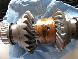

Cam shaft
Like the other components the shafts are visually inspected for wear, bending and corrosion but because it is hard to visually check the lobes for wear so we use a micrometer and we messure from the base to the nose because if it is worn to much the valve timing will be out.
Another thing to measure on the camshaft is the journels these are checked with a DIT guage which determines if there is any ovality or twist in the camshaft - both of which would effect how even the spin of the shaft is.
The camshaft bearings have to checked with a plasti-gauge to determine whether or not the gap is suficient to allow for lubricating oil to travel through the slot to be transfered onto the shaft, this is because of the huge amount of friction/heat. An important thing to know when it comes to the oil grove is that it increases in width as it is torqued down.


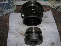
 Camshaft valve buckets
The valve buckets in this particular engine run with a pad of a certain thickness on the top of the bucket, the thickness of the pad determines how far the valve spring is compressed and how far the valve itself is opened. It also means that if wearing occurs it wears the pad which is easily replaced and not the whole bucket.


Cylinder block
Cylinder bore
We visually check the bore for pitting and scoring then we measure it in 6 different places within the bore these measurements when woked out tell us how much ovality and taper is in the bore from the stress the piston puts on the block especially on the thrust side.


Piston
-Again visually inspect for wear, check the piston rings are all intact.
-Measure the piston on the trust sides just above the skirt to determine how much wear has occured and compare it to the secifications.
-Measure the gap between the ends of the piston rings to make sure that they are going to hold compression from entering the crank shaft housing.
-The conrods need to be checked on a special straight edge tool to see if they have been bent or twisted because if they are damaged they will put unnecessary stress and force on the conrod bearings and crankshaft.

 
Crankshaft
Once we have inspected the crankshaft for damage we check the journals for runout using the DTI guage, the crankshaft has to be very strong to accomodate for 4 pistons running on top of it so it has to be turning exactly true within the bearings.


Important to remember
Always torque the crankshaft bearings, conrod caps and head in sequence and to specifications.
  

Wednesday, September 7, 2011

OHC vs Push rod and Side valve

over the years there have been a few different ideas for an efficient and cheap engines from k cycle to rotary, but only 2 have prevaled to be produced in mass OHC and Push rod

K-CYCLE

ROTARY

OHC
over head cams can be single or double shafts per cylinder head, they can operate straight on top of the valve buckets with spacing pads or the play in the valves can be closed by a hydrolic system controlled by the oil pump.
OHC can also controll rockers which push directly on the valves.
DOHC ment more valves in a smaller combustion chamber which resulted in more power, the earlier models of DOHC ran on 2 seperate gears but now one of the gears is run off the other by a scissor drive, this means that money is saved on manufacturing because it is that much more narrow.

compared to push rod OHC
-is more expensive because of the seperate head.
-more efficient because ther is no air pressure lost down the pushrod guide itself.
-harder to time with belt and chains because some push rod engines are run of gears.
-in an OHC there are more working parts than on a pushrod engine e.g. long timing chains/belts, hydrolic tentioners and oil feeders to the cams themselves.

A side valve system is essentuly a pushrod engine minus rockers with the valves directly on the end of the rod. - more jurasic park style


Monday, July 4, 2011

blogger comment

i rekon blogger is wikid because you can do your work in your own time, it is on going and you can bounce ideas off other fullaz in the class